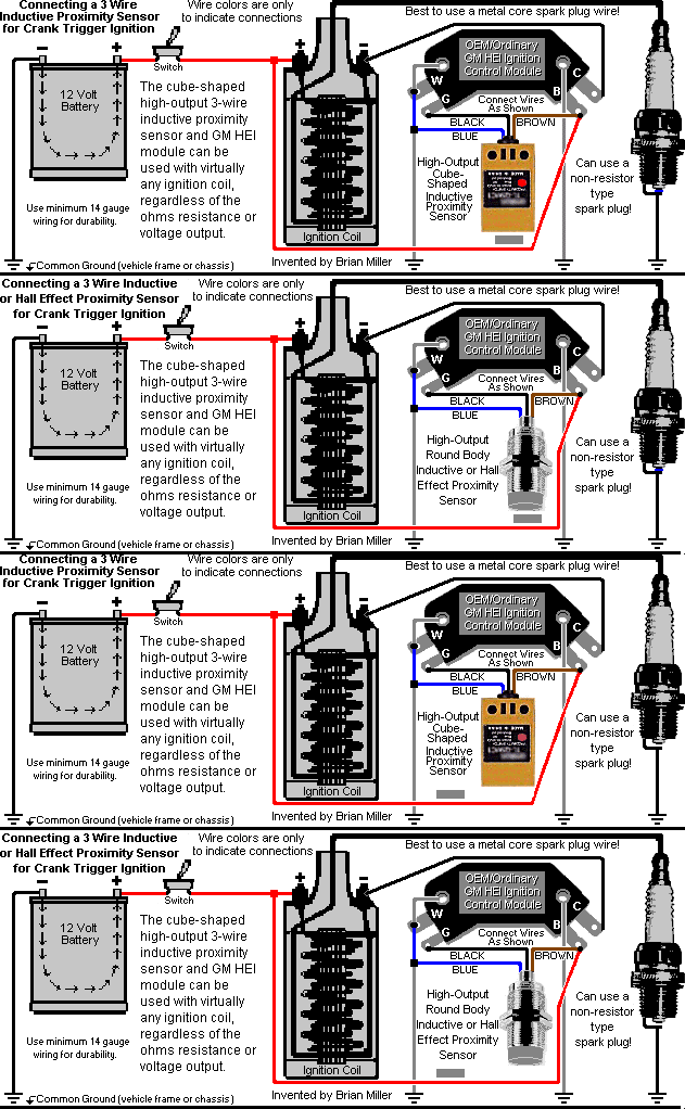
When it comes to understanding the intricacies of your vehicle’s ignition system, having a comprehensive 4 Pin Ignition Module Wiring Diagram can make all the difference. This diagram provides a visual representation of the wiring setup for your ignition module, helping you understand how everything is connected and working together.
Why 4 Pin Ignition Module Wiring Diagram are essential
Having a 4 Pin Ignition Module Wiring Diagram is essential for several reasons:
- It helps you understand the wiring setup of your ignition system.
- It allows you to troubleshoot any electrical issues effectively.
- It ensures that you connect the wires correctly when installing or replacing components.
How to read and interpret 4 Pin Ignition Module Wiring Diagram effectively
Reading and interpreting a 4 Pin Ignition Module Wiring Diagram may seem daunting at first, but with a little guidance, it becomes much easier:
- Start by identifying the key components in the diagram, such as the ignition module, ignition coil, and battery.
- Follow the lines connecting the components to understand how they are wired together.
- Pay attention to any symbols or color codes used in the diagram to indicate different types of connections.
Using 4 Pin Ignition Module Wiring Diagram for troubleshooting electrical problems
When faced with electrical issues in your vehicle’s ignition system, a 4 Pin Ignition Module Wiring Diagram can be your best friend:
- Use the diagram to identify any loose or disconnected wires that may be causing the problem.
- Check for any signs of wear or damage on the wires indicated in the diagram.
- Compare the actual wiring setup in your vehicle to the diagram to pinpoint any discrepancies.
Importance of safety
Working with electrical systems can be dangerous if proper precautions are not taken. Here are some safety tips to keep in mind when using 4 Pin Ignition Module Wiring Diagram:
- Always disconnect the battery before working on any electrical components.
- Avoid working on the ignition system when the engine is running.
- Use insulated tools to prevent electric shocks.
- If you are unsure about any part of the wiring diagram, consult a professional mechanic for assistance.
4 Pin Ignition Module Wiring Diagram
4 Pin Ignition Module Wiring Diagram

4 Pin Ignition Module Wiring Diagram

1994 Ford Ranger Ignition Wiring Diagram – Wiring Diagram Explained

4 Pin GM Module Back To Stock – Holley Motor Life

GM 4-Pin HEI Electronic Ignition Control Module Wiring Connections

4 Pin Ignition Module Wiring Diagram

4 Pin Ignition Module Wiring Diagram

[DIAGRAM] Gm Hei 4 Pin Ignition Module Wiring Diagram – MYDIAGRAM.ONLINE
![4 Pin Ignition Module Wiring Diagram [DIAGRAM] Gm Hei 4 Pin Ignition Module Wiring Diagram - MYDIAGRAM.ONLINE](http://gpzweb.s3-website-us-east-1.amazonaws.com/Ignition/CbHeiModCavCoil.gif)